This tool uses dBi or dBd to calculate the linear gain of an antenna relative to either an isotropic antenna or a half-wave dipole.
Calculator
Enter the value of gain in either dBi or dBd.
Formula
GdBd = GdBi – 2.15
where
- GdBi is the dB antenna gain relative to isotropic
- GdBd is the dB antenna gain relative to a half-wave dipole
Gi = 10GdBi/10
Gd = 10GdBd/10
Example Calculation
For a value of 7 dBi, the linear values of gain relative to isotropic and half wave dipole are: 5 and 3.06, respectively.
For a value of 7 dBd, the linear values of gain relative to isotropic and half wave dipole are: 8.22 and 5.01, respectively.
👉 Wikipedia article on Antenna Gain
Background
What is an isotropic antenna?
An isotropic antenna is a theoretical concept rather than a practical device. It’s imagined as a point source in space that radiates electromagnetic energy equally in all directions. This means it has no preferred direction of radiation; its pattern is a perfect sphere.
In antenna theory, the isotropic antenna serves as a reference to measure the performance of real antennas. The term “isotropic” itself derives from Greek, where “iso” means equal and “tropos” means way or direction, highlighting the uniform radiation in all directions.
Since it’s an idealized concept, no physical isotropic antennas exist. However, it’s very useful for comparing and understanding the performance of actual antennas. For instance, when you hear about an antenna’s gain described in dBi, the “i” stands for isotropic. A gain of 3 dBi, for example, means the antenna can transmit or receive energy 3 dB stronger in its preferred direction than an isotropic antenna would radiate in any direction. This comparison provides a baseline for evaluating antenna designs in a consistent manner.
What is a half-wave dipole antenna?
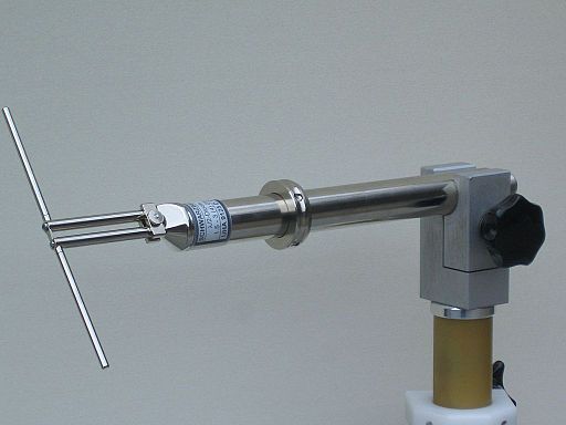
A half-wave dipole antenna is a simple and widely used type of antenna that is particularly effective for radio frequency transmission and reception. Its operation is based on resonating at a frequency where the length of the antenna is half the wavelength of the signal it is designed to transmit or receive.

Here are some key points about half-wave dipole antennas:
- Length: The total length of a half-wave dipole is approximately half the wavelength (λ/2) of the frequency it is intended to use. This length allows the antenna to resonate at that frequency, leading to efficient radiation and reception of radio waves.
- Design: It typically consists of two rods or wires that extend outward from the center, where they are connected to a feed line (such as a coaxial cable). This feed line is accommodated by a gap in between. It is then connected to a radio transmitter, receiver, or transceiver.
- Radiation Pattern: The half-wave dipole has a directional radiation pattern that is shaped like a doughnut. It radiates most of its energy perpendicular to the axis of the antenna, with minimal radiation from the ends. This pattern makes it effective for many basic communication needs.
- Impedance: At its design frequency, a half-wave dipole typically presents an impedance of around 73 ohms, making it relatively easy to match with standard 50-ohm coaxial cable using appropriate matching devices.
- Applications: Due to its simplicity, effectiveness, and relatively broad bandwidth, the half-wave dipole is used in a wide range of applications, from amateur radio to commercial broadcasting and beyond. It serves as a fundamental building block for more complex antenna designs.
